Click
image for diagram
|
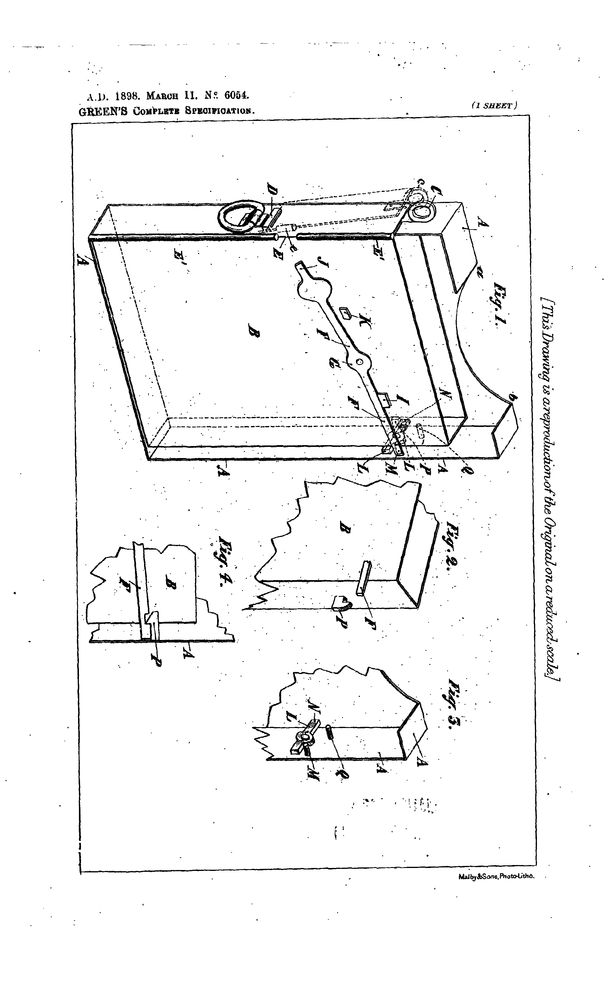
Improved Coin Receiver or Cash Box with Automatic Fastening Appliances when the Box is
Pushed in the Coin Freed Gas Meter
Casing.
6054. Green, W. 0. March 11. Gas meters; money boxes.-Improvements
relating specially to the invention described in Specification No. 25,272, A.D. 1894. When the open cash-box B is thrust into the shell A upon the meter casing, a nose P upon it slips under a latch L on the shell so that it cannot be withdrawn till a lever F for disengaging the latch has been operated. The cash-box is secured from unwarranted abstraction by a strap and a padlock through an eyelet C, the gap E in the heading being closed by a lug on the strap.
Patent applied for on 11 March 1898
Patent GB189806054A
|
|
Click
image for diagram
|
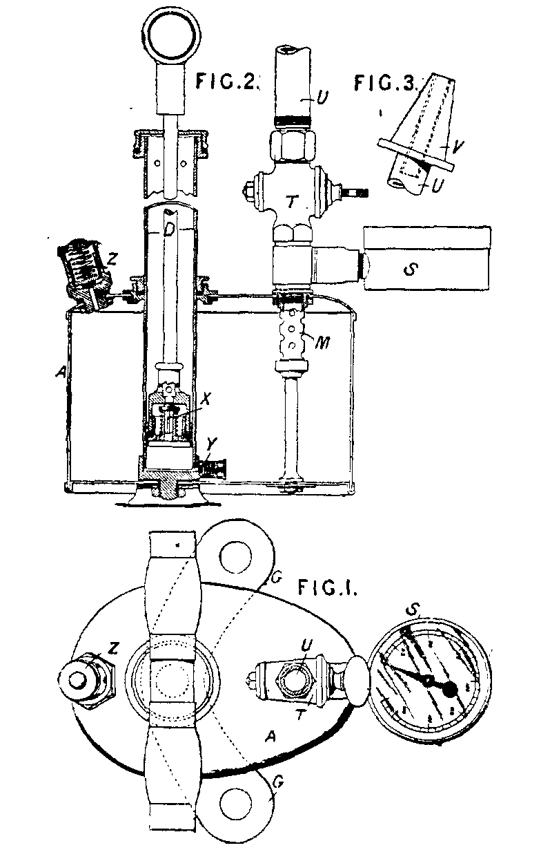
Improvements in Compressor Pumps.
20,311. Green, W. O. Sept. 26. Compressing; storing under pressure.-A pump is combined with a storage reservoir A of such a form that it can easily be carried on a bicycle by a workman employed in clearing obstructions in gas mains and pipes. The reservoir is pear-shaped in horizontal section, is made as light as possible, and is stayed by the pump barrel D and the delivery pipe M. Foot-plates G project on each side to steady the apparatus during charging. The air enters the pump through a valve X in its piston, and is discharged through the valve Y into the reservoir. The delivery pipe U is fitted with a conical india-rubber nozzle V, a stop-cock T, and a pressure gauge S. The reservoir has a safetyvalve Z.
Patent applied for on 26 September 1898
Patent GB189820311A
|
|
Click
image for diagram
|
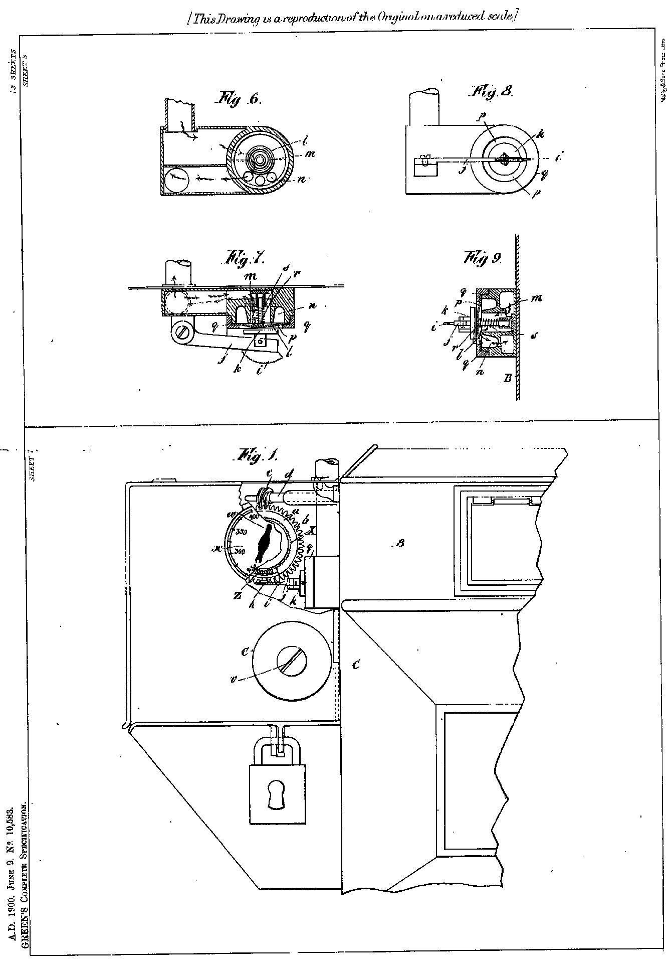
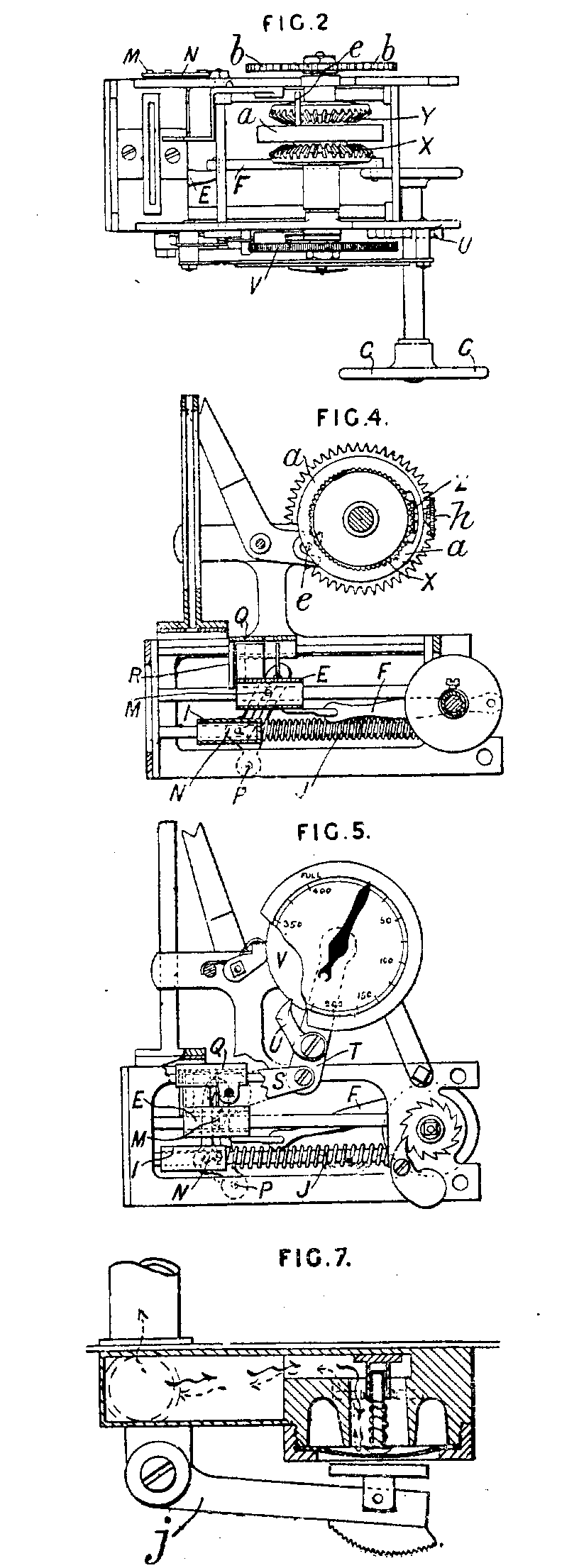
Improved Construction of Coin Freed Mechanism and Valves therefor, for Gas and other like
Meters.
10,583. Green, W. O. June 9. Gas meters.-Relates to coin-freed apparatus which can readily be fixed to existing gas and like meters. The mechanism is contained in a casing which can be secured to the side of any meter. Actuating - mechanism ; coin action ; coindischarging mechanism.-When a coin of the required value is dropped through the coin-slit, it falls through a slotted plate Q, Figs. 4 and 5, and through the slotted travelling carriage E, and rests on the travelling platform I. A pin M projecting from the carriage passes through a slot in a link N, which is pivoted at P. A pin projecting from the platform also engages the slotted link. When the carriage is moved along its guide-rods by rotating the band-wheel C, the platform is also moved in the same direction, against the springs J, but at a reduced speed. Thus the coin moves along the platform, and at about the termination of the stroke falls from the carriage E into the till. The movement of the hand-wheel is conveyed to the carriage E by a crank disc and connecting-rod F. The plate Q is caused to move with the carriage by its engagement with the coin, and by means of a link S swings the lever T carrying the pawl U which moves over the ratchet-wheel V. When the hand-wheel is released after a halfrevolution, the springs J return the platform I, and through the slotted link N the carriage E, which again returns the plate Q by pressing on a depending projection R. The lever T is thus returned to its former position, the pawl U rotating the ratchet-wheel V and with it the bevel-wheel X. A bevel pinion Z is in gear with the wheel X and with a similar wheel Y, which is mounted on a spindle carrying a worm-wheel b gearing with a worm on the spindle of the registering-mechanism of the meter. The pinion Z is mounted in a revoluble frame or ring a on a spindle which also carries a small toothed wheel h. When the wheel X is rotated as described above, the pinion Z moves round over the fixed wheel Y, and the wheel h is moved out of gear with a toothed segment on the lever j by which the valve is closed. As shown in Fig. 7, the valve is of the diaphragm type, and is opened by a spring plunger when the wheel h is moved away as described above. After the valve is opened, the registering-mechanism of the meter is started and rotates the wheels b and Y, so that the pinion Z and wheel h are rotated in the reverse direction about the fixed wheel X, and the wheel h eventually engages with the segment on the lever J and closes the valve. Coin - slit closing-devices.-When the required coins have been successively dropped into the meter and the hand-wheel correspondingly actuated, a pin e in the frame or ring a engages a lever f and throws it across the coin-shoot, so that no more coins can be inserted. Fraud, preventing.-A coin of smaller size than that desired does not engage the plate Q, so that the valve opening mechanism cannot be operated.
Patent applied for 9 Jun 1900
Patent GB190010583A
|
|
Click
image for diagram
|
Improvements connected with Coin Freed Mechanism for Gas and like
Meters.
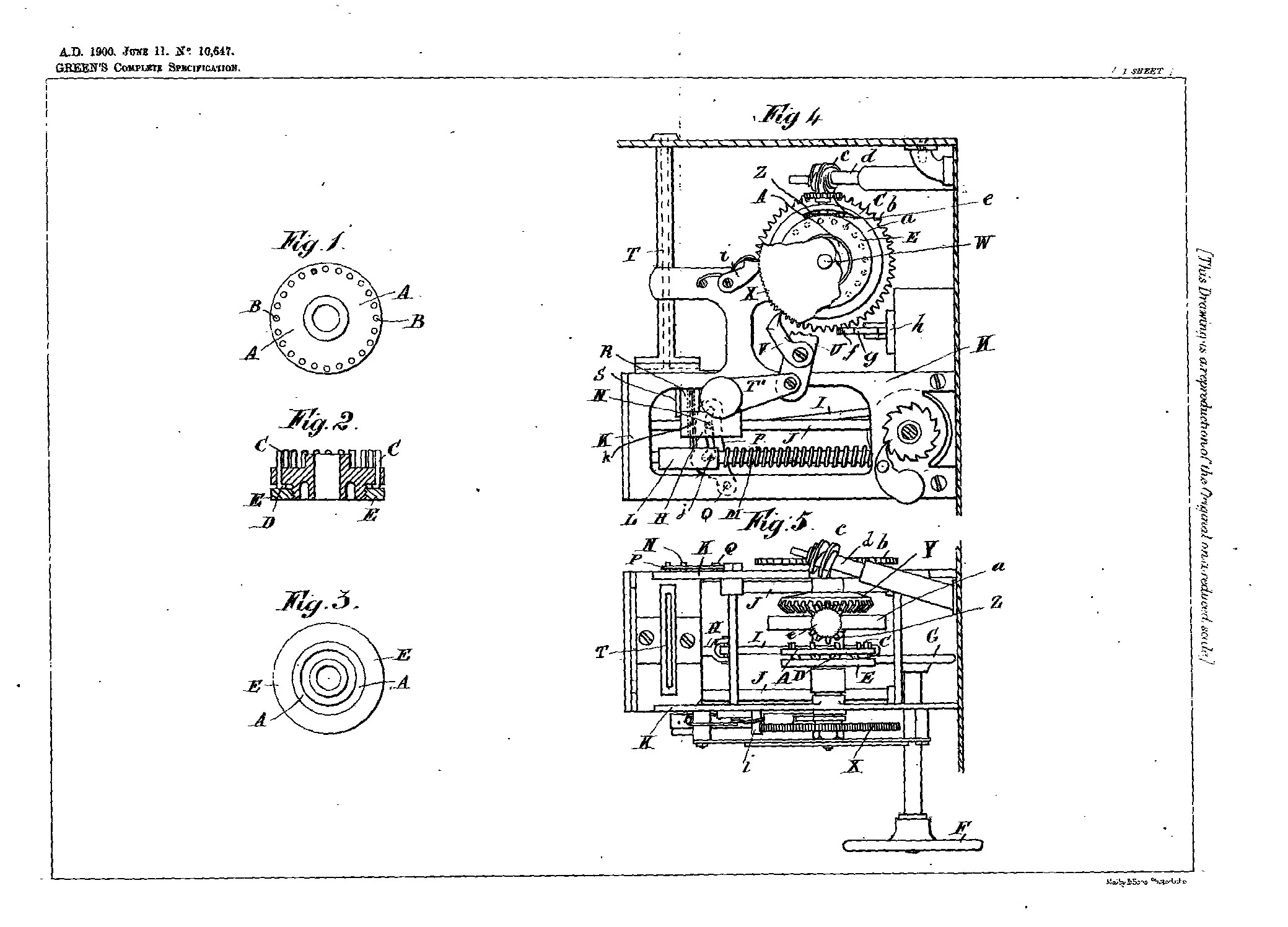
10,647. Green, W. O. June 11. Toothed wheels f o r coin-freed gas and liquid meters. Fig. 2 shows a wheel by means of which the amount of gas or liquid supplied per coin can be varied. A perforated disc has a number of headed pins C secured in it by means of a screwed ring E or otherwise. By varying the number of pins, the amount of gas or liquid supplied is adjusted.
Patent applied for 11 June 1900
Patent GB190010647A
|
|
Click
image for diagram
|
Improved Construction of Buckle or Fastening Device.
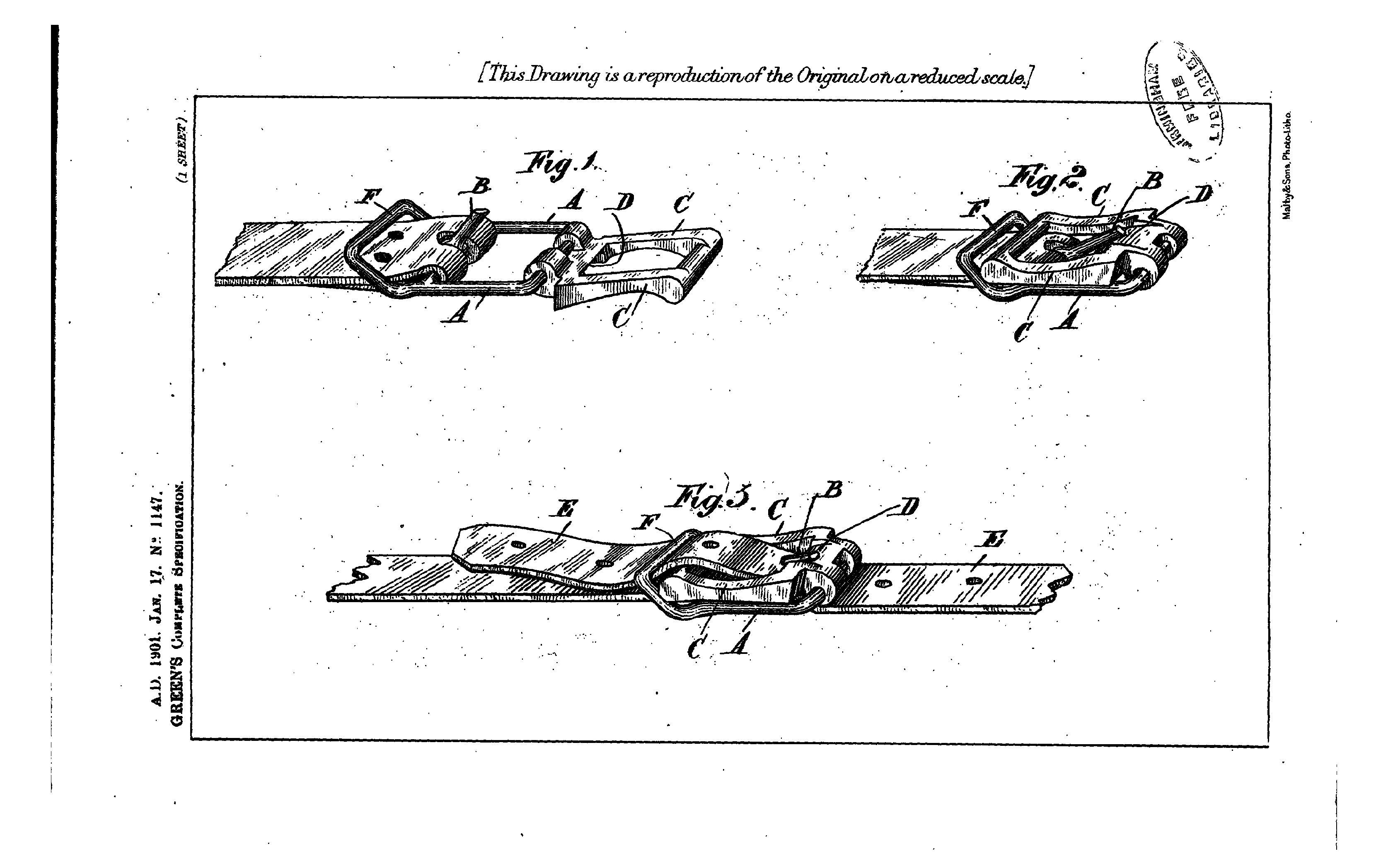
1147. Green, W. O. Jan. 17. Buckles.-A buckle, which can be easily released, and is applicable to harness, military equipments, and fire-brigade and other uses, consists of a frame A having a short tongue B, a loop F, and a pivoted frame C adapted, when folded into the position shown in Fig. 3, to engage the end of the tongue B. The strap E is passed up through the frames A, C, and under the loop F. The strap is released by turning the frame C into the position shown in Fig. 1. Spring lugs may be provided to hold the frames together, and prevent accidental release.
Patent applied for on 17 January 1901
Patent GB190101147A
|
|
Click
image for diagram |
Improvements relating to Coin-operated Machines for the Delivery of Goods in Exchange for Coins Inserted therein.
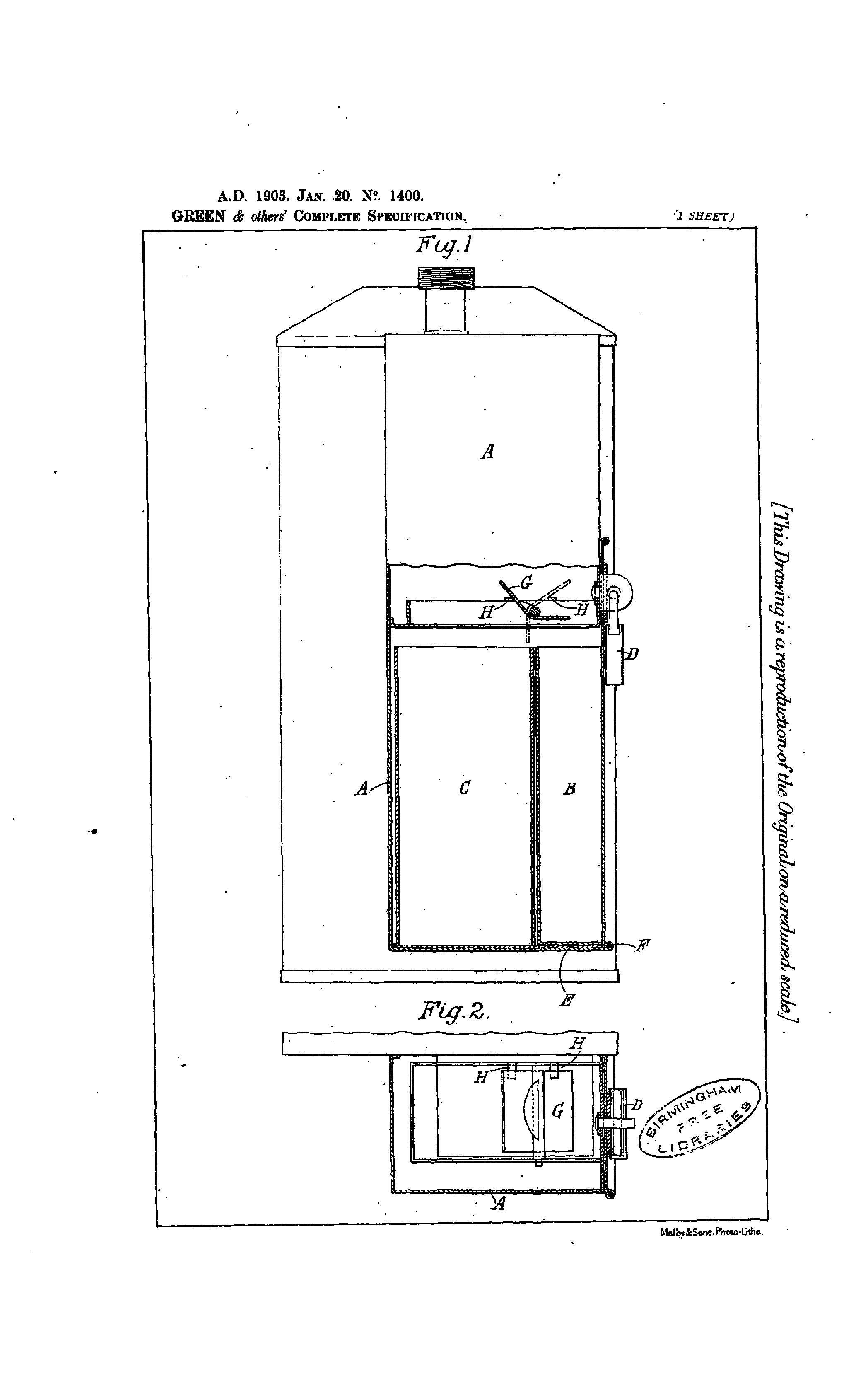
Green, W. O., and Glover & Co., G. Jan. 20. Sale apparatus ; gas meters. - Relates to the moneybox arrangements. Money boxes; casings; fraud, preventing.-Two cash receptacles B, C are provided, the outer one of which B, secured by a padlock D, seems the only one to a thief but receives only the first coin dropped in, while the inner one , securing a part of the casing, receives all the others. The first coin strikes a diverting rocking plate G, which turns over between stops H from the position shown in full lines to that shown in dotted lines, at which it remains to divert the coins into the rear receptacle. The rear receptacle preferably has its base E protruding to the beading F of the casing.
Patent applied for on 20 January 1903
Patent GB190301400A
|
|
Click
image for diagram
|
Improvement connected with Gas Cooking Ranges.
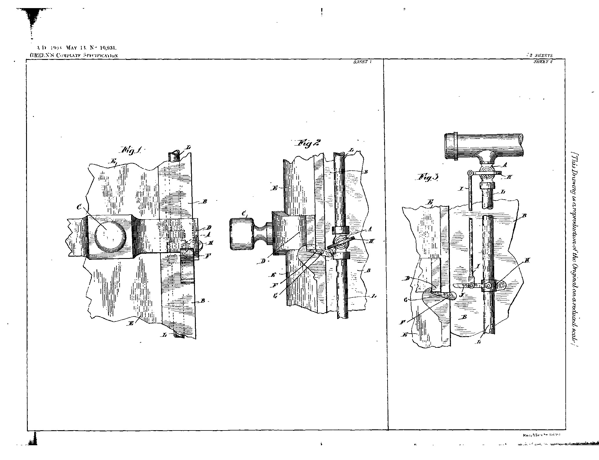
10,931. Green, W. O. May 13. Gas cooking- stoves. - The oven door of a gas cook. ing-range is released automatically to allow it to open when the gas cock is opened, in order to prevent explosions by allowing the gas to escape from the oven, and to indicate that the gas is turned on. The latch D is lifted by a pivoted lug F operated directly by the handle H or the stop-pin of the gas cock or by a second pivoted lug operated by a cam or a spring- raised or other rod connected to the plug.
Patent applied for on 13 May 1903
Patent GB190310931A
|
|
Click
image for diagram
|
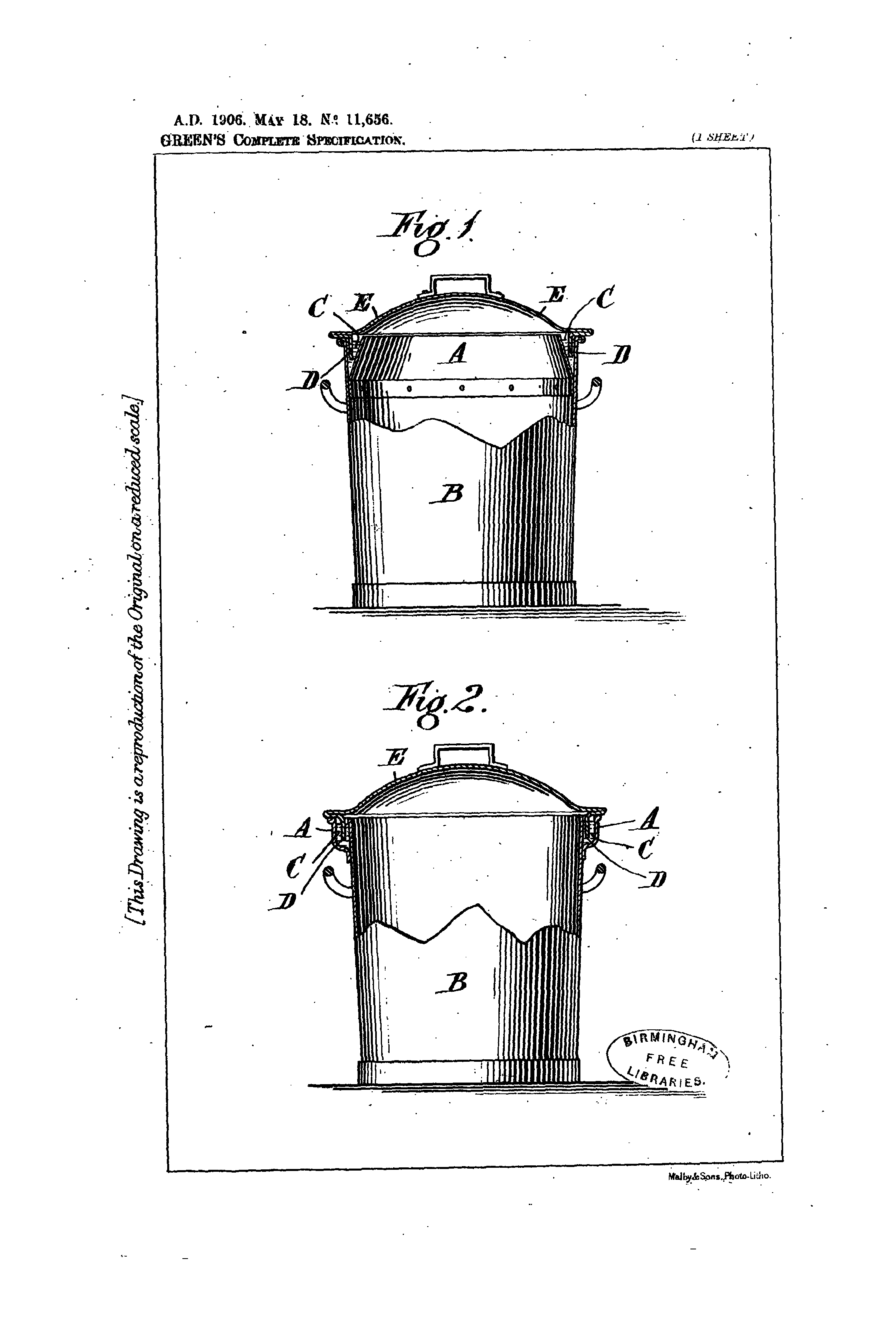
Improvement connected with Portable Dust Bins and the like.
11,656. Green, W. O. May 18. Dust - bins. - A flange D on the lid dips, to form a water seal, into an internal or external channel A containing water. When external, the channel is rectangular in section.
Patent applied for on 18 May 1906
Patent GB190611656A
|
|
Click
image for diagram
|
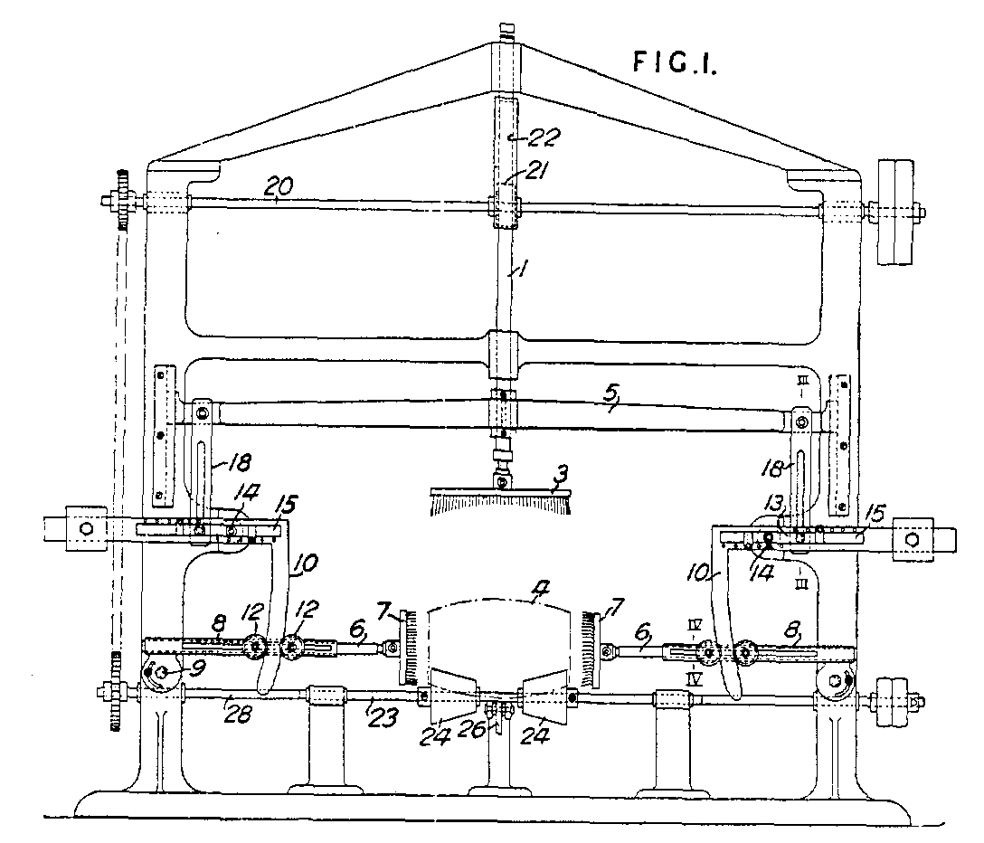
Improvements in cask washing machines
305,692. Green, W. O., and Thompson (Wolverhampton), Ltd., J. Nov. 3, 1927. Cleansing casks.-A cask-washing machine comprises a vertical slidable shaft 1 carrying one or more brushes 3 at its lower end, two slidable cross spindles 6 having brushes 7 at their inner ends, each spindle being engaged through a lost motion connection bv one arm of a bell crank lever 10 which is mounted on the machine frame and has its other arm weighted or spring controlled, a cross frame or beam 5 carried by the vertical shaft 1 and connected to the bell crank levers 10 by slotted links 18, and means for removing the members and brushes free. from the cask at certain intervals. The shaft 1 carries a rack 22 adapted to be engaged by a mutilated, gear wheel 21 on a cross shaft 20 to raise the brush 3 and allow it to drop on to a cask 4 supported by cones 24 on shafts 23 rotated either independently or from the shaft 20. As the cross bar 5 descends, the links 18 depress the outer ends of blocks 13 pivoted at 14 to the main frame and adjustable in slots 15 in the horizontal arms of the bell crank levers 10. The vertical arms of the levers 10 are thereby moved inwards and with them the spindles 6 and brushes 4 the spindles being mounted in slotted bearings 8 and being provided with rollers 12 which are engaged by the levers 10. The bearings 8 are adjustable angularly about pivots 9 on the main frame. When the brushes 3, 7 have operated on the cask, the mutilated pinion 21 frees them therefrom and a cam on a shaft 28 driven from the shaft 20 actuates a lever 26 to eject the cask from the cones 24.
Patent applied for on 3 November 1927
Patent GB305692A
|
|
Click
image for diagram
|
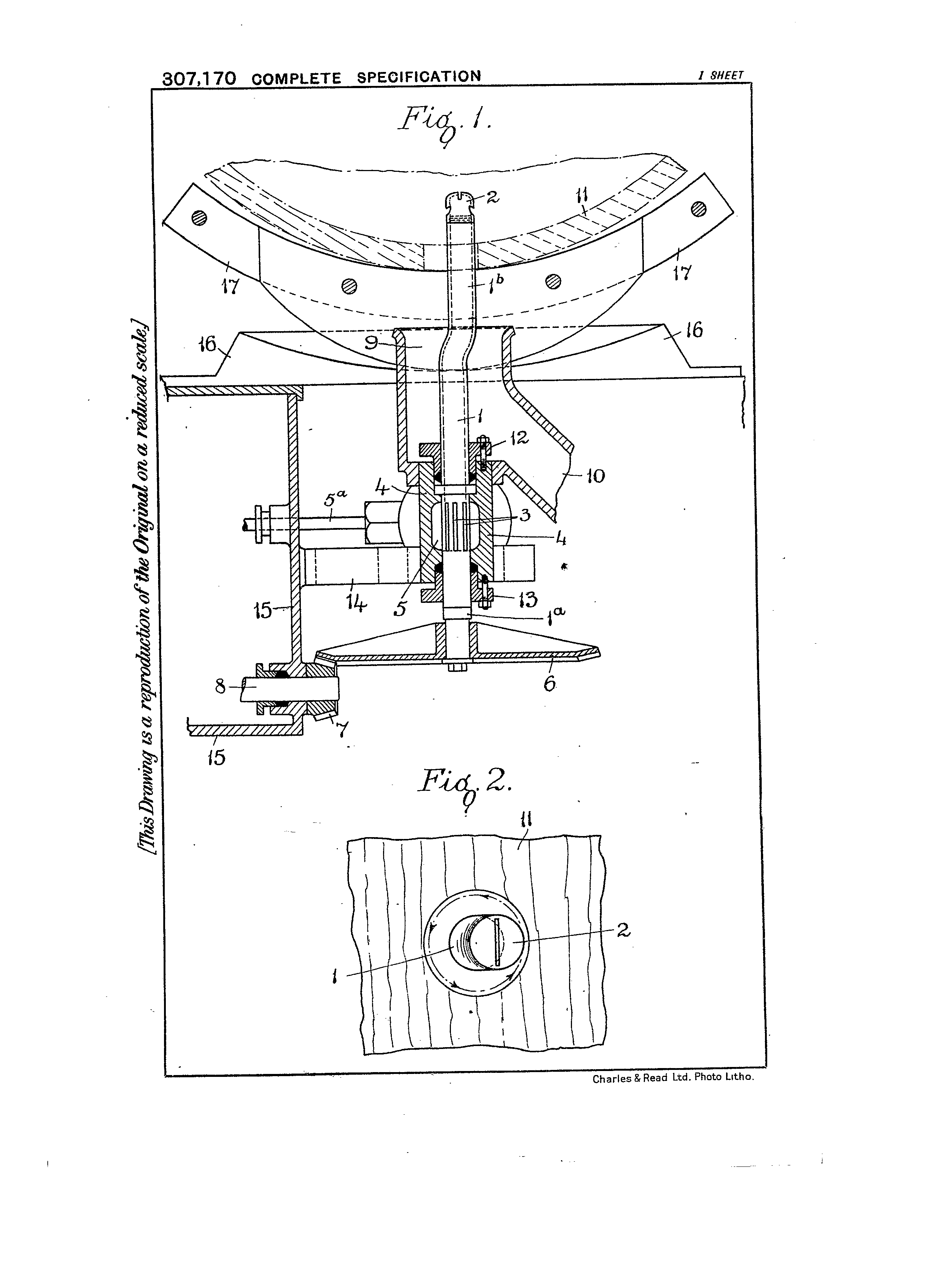
Improvement in or connected with cask washing and sterilising
machines
307,170. Thompson (Wolverhampton), Ltd., J., and Green, W. O. Jan. 27,
1928. Rotary apparatus. - Relates to cask washing apparatus of the type
having a rotary nozzle for spraying the interior of the cask &c.
According to the invention a machine comprises a revolvable tube 1 having
inlet openings 3 mounted in a bollow block 4. The tube has a cranked end
1<b> carrying the nozzle 2 and a gear wheel 6 at the other end which
is closed. Steam, water &c. is supplied to the block by pipes
5<a> and a rotary motion is imparted to the tube through the gear
wheels 6, 7.
Patent applied for on 27 Jan 1928
Patent GB307170A
|
|
Click
image for diagram
|
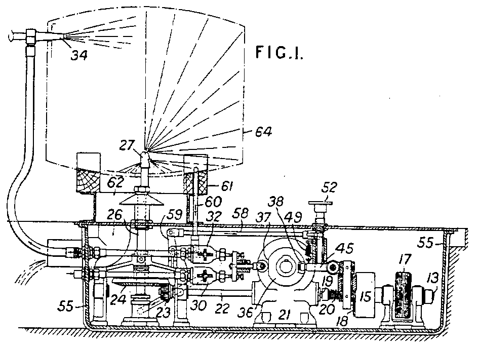
Improved construction of apparatus for cleansing the insides of casks, barrels and the like
384,056. Cleansing casks &c. GREEN, W. O., 20, Culverhouse Gardens, Streatham, London. Nov. 13, 1931, No. 31470. [Class 21.] In a cask, barrel, &c. cleaning machine the supply of cleansing fluid and the rotation of the feed pipe are controlled by a foot- or handoperated mechanism which cannot be operated until the cask &c. is properly positioned for cleansing. The mechanism is driven by an electric motor or other prime mover (not shown) which through a chain 17 drives a shaft 13 which drives an aligned shaft 19 through a clutch 15, 18 controlled by a spring 20, and this through reduction gear contained in a case 21 drives a second aligned shaft 22 which through bevels 23, 24 rotates a pipe 26 carrying a nozzle 27. Water and steam are supplied to pipes 26, 34 respectively through valves in casings 30, 32, the valve spindles being actuated by a flat 37 on a cam 36. When a cask 64 is placed on the chocks 61 a rod 60 is depressed and actuates a bell crank 59 and rod 58 to free a pedal 52 which may then be depressed to move a bell crank 45 against a spring 49 and engage the two clutch members 15, 18 so that the nozzle-rotating mechanism is actuated until a projection 38 on the cam 36 disengages the clutch. The mechanism is contained in a tank 55 and the cask drains into a smaller tank 62.
Patent applied for on 13 November 1931
Patent GB384056A
|
|
Click
image for diagram
|
Improved construction of machine or apparatus for cleansing the outsides of casks, barrels and the like
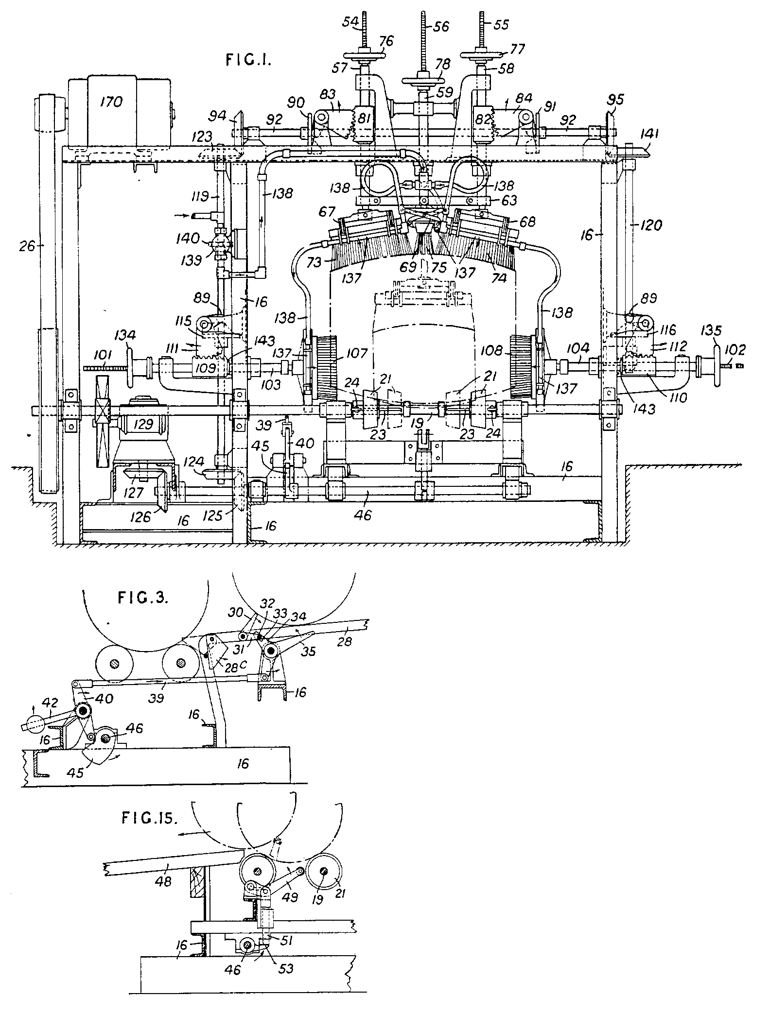
386,389. Cleaning casks &c. GREEN, W. 0., 20, Culverhouse Gardens, Streatham, London. Nov. 13, 1931, No. 31469. [Class 21.] A machine for cleaning the outsides of casks &c. comprises a framework 16, Fig. 1, carrying two shafts 19, each carrying two rubber &c. covered rollers 21, which are fixed or adjustable to the size of cask by keyways 23 and thumb-screws 24, the shafts being operated to rotate the cask by a belt 26 which connects an electric motor 170. The casks are fed to the rollers along sloping tracks 28, Fig. 3, and are stopped and released by two doublearmed rocking levers, arms 30 of which are free while the others 31 are connected by a rod 32 whose ends engage slots 33 in arms 34 of a second pair of double-armed rocking levers of which the other arms 35 are free, this second pair of levers being pivoted on the frame 16, and being rocked intermittently by means of a rod 39, and a rocking lever 40 having a weighted arm 42 actuated through a cam 45 on a shaft 46 driven by bevel gearing 126, 127 through a reduction gear 129 from the driven shaft 19. At the end of the track 28 nearest the cask plates 28c are pivoted which occupy the position shown for large casks but are turned to the dotted position for small casks to ensure the feeding of the cask on to the rollers. The casks are delivered from the machine along a track 48, Fig. 15, by a forked frame 49 lifted at the appropriate moments by a rod 51 actuated by a tappet 53 on the shaft 46. Top brushes 73, 74 and end brushes 107, 108 are moved at the appropriate moments to and from the cask by means of tubular carriers 57, 58, 103, 104 within which are secured adjustably screwed rods 54, 55, 101, 102 carrying the brushes and adjusted by hand-wheels 76, 77, 134, 135, the tubular carriers being moved by means of toothed sleeves 81, 82, 109, 110 engaged by toothed quadrants 83, 84, 111, 112 carrying rollers 89 actuated by tappets 90, 91, 115, 116 on shafts 92, 119, 120 actuated from the shaft 46 through bevel gearing 124, 125, 123, 94, 95, 141. Springs 143 ensure the return movement of the end brushes 107, 108. Slight lateral adjustment of the end brushes to accommodate casks of slightly varying length is provided for by making the connection between the tubular carriers 103, 104 and the screwed rods 101, 102 resilient. A central top brush 75 is also employed, the three tubular carriers 57, 58, 59 being connected at the bottom by a strap 63. For small casks this centre brush only is used at the top, being rotated through 90‹ as shown in chain dotted lines in Fig. 1. The brushes 73, 74, 75 are carried by pivoted links 67, 68, 69 which allow adjustment to the shape of the cask. Water &c. spray pipes 137 are attached to all the brush frames, and are connected by pipes 138 to a water supply controlled by a valve 139 actuated by a cam 140 secured to the shaft 119, so that cleansing fluid is supplied only while the cask is being cleansed. The apparatus is mounted over a well 141 which receives the waste fluid.
Patent applied for on 13 November 1931
Patent GB386389A
|
|
Click
image for diagram
|
Improvements in means for retaining meat and the like in position on dishes during carving
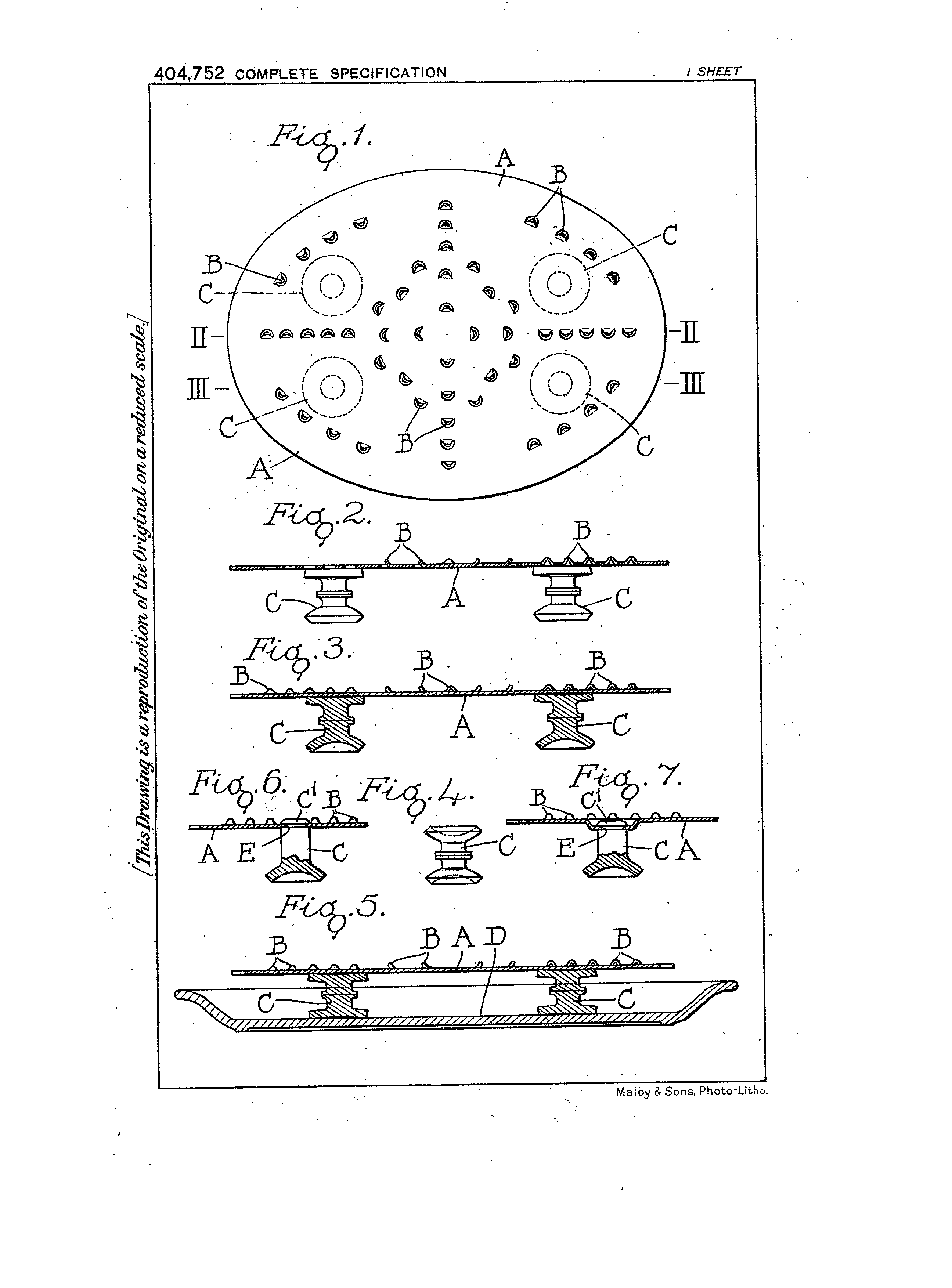
404,752. Meat-carving appliances. GREEN, W. O., 20, Culverhouse Gardens, Streatham, London. Aug. 17, 1932, No. 23073. [Class 28 (ii).] A device for retaining meat in position on dishes during carving comprises a plate having sharp projections on the top side to engage the meat and suction devices on the underside to engage the dish which are directly attachable to the plate merely by hand pressure and which hold the plate above the rim of the dish. The metal plate A, Fig. 5, has projections B punched out of it and is held on the dish by double suction holders C which engage both the plate A and the dish. Alternatively a single suction holder C, Fig. 7, may be used having a button head C<1> which makes direct snap engagement with a hole E in the plate or in a recess therein.
Patent applied for on 17 August 1932
Patent GB404752A
|
|
Click
image for diagram
|
Improved construction of machine or apparatus for cleansing the outsides of casks, barrels and the like
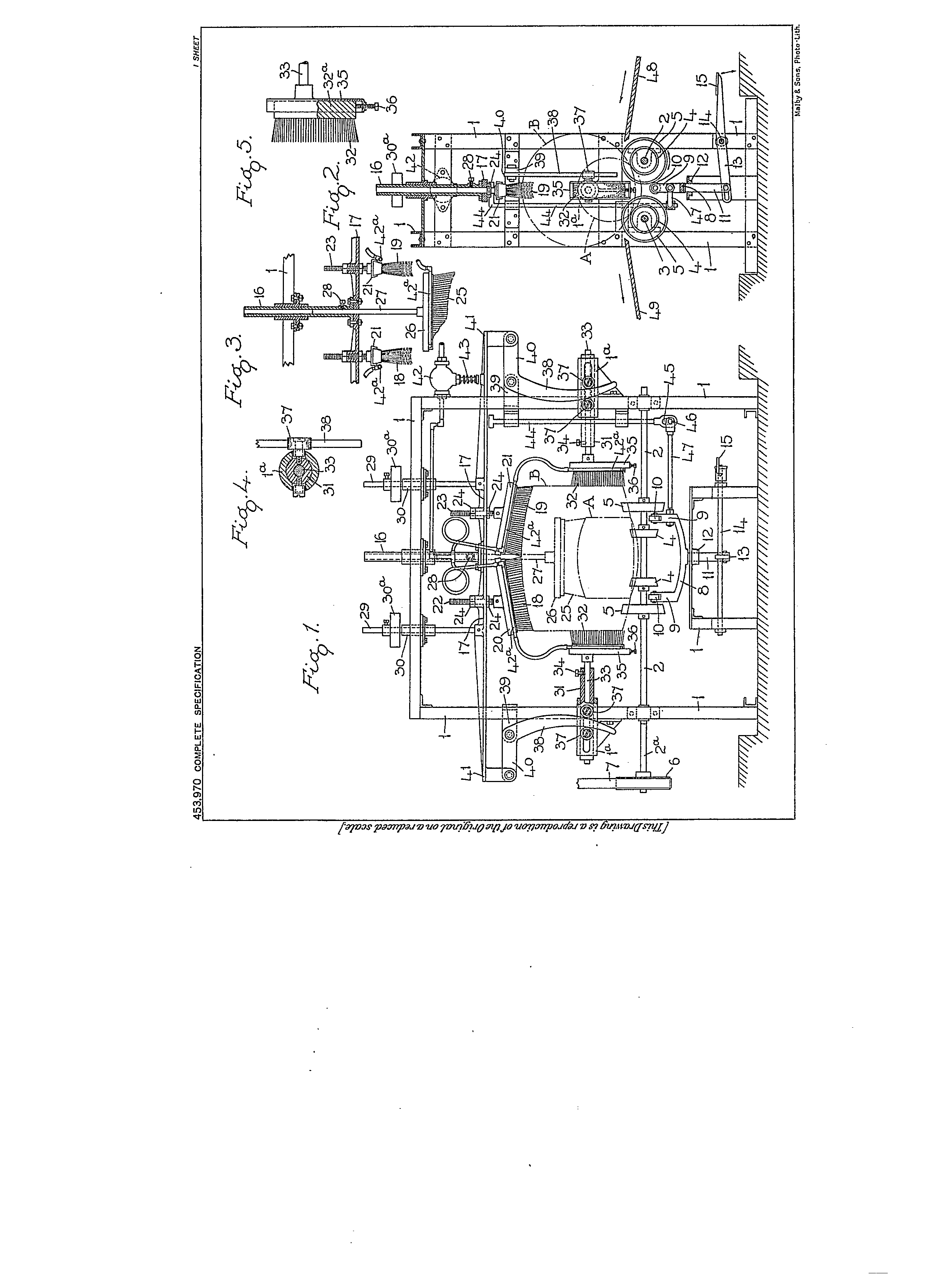
453,970. Cleaning casks. GREEN, W. 0., 20, Culverhouse Gardens, Streatham, London. June 28, 1935, No. 18542. [Class 21] A machine for cleaning the outsides of barrels comprises a frame 1, Figs. 1 and 2, carrying two shafts 2, 3 each of which has two pairs of rubber-covered rollers 4, 5 adapted to support a small or a large cask. Shaft 2 is driven by a belt 7 from a motor &c. The cask is lifted from the rollers by a frame 8 having pillars 9 and rollers 10 which contact the barrel and a stem 11 is pivoted to a lever 13 actuated by a pedal 15. A post 16 slidable in the upper part of the frame 1 carries a plate 17 to which brushes 18, 19 are adjustably secured, preferably by holders 20, 21 having screwed posts 22, 23 engaged by nuts 24. For small casks a single brush 25 is employed. Plate 17 carries guide posts 29 on which weights 30a are mounted to ensure contact between the brushes and the cask, the weights also limiting the downward movement of plate 17. Side brushes 32 are carried on slidable members 31 actuated by a curved lever 38 engaging between rollers 37, the arrangement being such that vertical movement of plate 17 produces lateral movement of brushes 32. The brushes 32 are adjustable vertically in grooves in their holders 35 by screws 36. A valve 42 supplying water to sprays 42<a> is controlled by the movement of plate 17 through a spring plunger 43. Plate 17 is actuated with lost motion from the lifting device 8 by a rod or rods 44. Sloping tracks 48, 49 facilitate feeding and removing of the barrels. Depression of pedal 15 disengages the brushes and stops the water supply; raising of the pedal engages the brushes and opens the water valve.
Patent applied for on 28 June 1935
Patent GB453970A
|
|
Click
image for diagram
|
Improved construction of apparatus for cleansing the insides of casks, barrels and the like
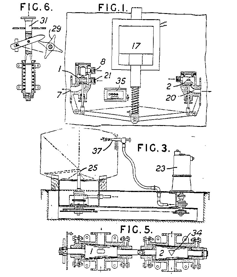
453,610. Cleansing casks. GREEN, W. 0., 20, Culverhouse Gardens, Streatham, London. April 8, 1935, No. 10846. [Class 21] In a cask-cleansing apparatus, valves 1, 2, Fig. 1, actuated by a solenoid 17 admit water or steam or both to the cask by nozzles 25, 37, Fig. 3, nozzle 25 being rotated by an electromotor 23 which may supply current to the solenoid. In the position of the valves 1, 2 shown in Fig. 1, steam is shut off by valve 2 but water enters the barrel by passages 21, 8. In the other position of the valves, water and steam enter simultaneously by passages 7, 20. In another form the valves are plug taps 1, 2, Fig. 5, and are connectable e.g. in the manner shown. The valves are actuated by hand or by the foot or by the weight of the barrel on plunger 31, Fig. 6, which actuates a starwheel 29 and so actuates the valves. The steam inlet 34 is triangular to ensure a gradual opening of the valve. In all forms the valves are shut off manually or in some other non-automatic way and in any form a counter 35, Fig. 1, may be employed to indicate the number of times the valve has been actuated. Specification 384,056 is referred to.
Patent applied for on 8 April 1935
Patent GB453610A
|

